
Working Principle and Structural Features of the Top-Roll Universal Plate Bending Machine
The upper-roll universal CNC three-roll plate bending machine incorporates technology introduced from Japan. Following years of domestic development, it is now widely employed across various industries. Below is an outline of the composition of this CNC three-roll plate bending machine: the main body comprises the primary drive assembly, horizontal traverse assembly, upper roll assembly, support roll assembly, tilting mechanism, left and right frames, base, and balancing device.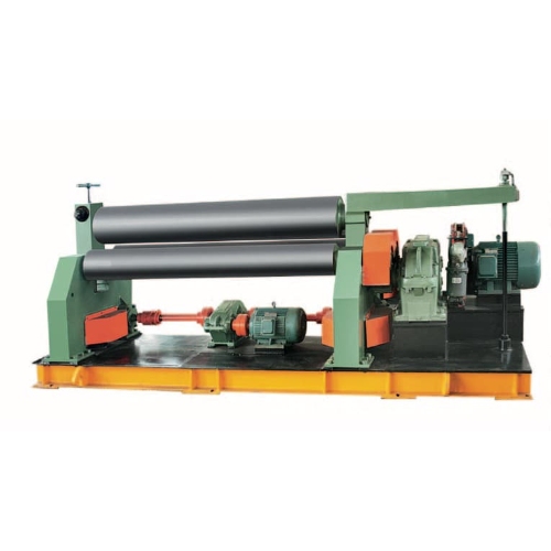
1. Main drive system
Located to the right of the machine, it comprises the main motor, pulley, reduction gearbox, output gear, and other components.
Capable of forward and reverse rotation, it supplies the working power. Torque is transmitted through the main reduction gearbox, output gear, and lower roller gear to the lower roller, causing it to rotate. This rotation, coupled with friction, drives the sheet material feed to accomplish the rolling operation.
2. Lower rollers and horizontally moving components
The lower roll assembly comprises the lower roll, lower roll bearing housing, lower roll shaft sleeve, and lower roll gear.
The lower roll is fabricated from high-quality carbon steel, undergoes full quenching and tempering, with the roll surface hardness rated at HRC 48–55.
The horizontal movement mechanism is powered by a horizontal drive motor. Through a worm gear transmission and a screw transmission mechanism, it drives the frame and upper roll assembly to move horizontally, thereby achieving the pre-bending of the workpiece.
3.Upper roller assembly
Comprising a hydraulic cylinder, bearing housing, bearings, and upper roller.
The upper roller is drum-shaped to compensate for partial deflection caused by deformation.
Manufactured from 42CrMo steel, it undergoes quenching and tempering treatment, with the roller surface hardness ranging from HRC 56 to 62.
4. Roller assembly
Comprising a roller assembly, an inclined wedge mechanism, and a screw mechanism.
The adjusting screw drives two opposing sets of inclined wedges to converge or diverge, thereby raising or lowering the idler assembly.
Idlers are fabricated from 45 steel and undergo quenching and tempering treatment.
5. Overturning device
Comprising a pin, ram, tilting hydraulic cylinder, and support bracket.
The hydraulic cylinder operates to tilt and reset the tilting frame. When the tilting frame is tilted, the workpiece can be removed axially from the tilting end.
6. rack
Comprising a frame, slide plate and bearing bush.The frame body is a welded component, annealed and shot-blasted. It mounts the main hydraulic cylinder and drives the upper roller assembly for horizontal movement.
7. Base
Box-type welded structure, annealed and shot-blasted. Used for mounting various components.
8. Balancing device
Comprising crossbeams, support plates, tie rods, and other components.
Used to secure the rear end of the upper roller, ensuring it remains balanced after the overturning frame has been tilted, thereby facilitating the removal of the workpiece.
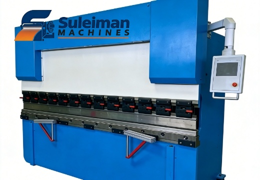 Bending on a Budget: Why the Torsion Bar CNC Press Brake is Still the ROI King
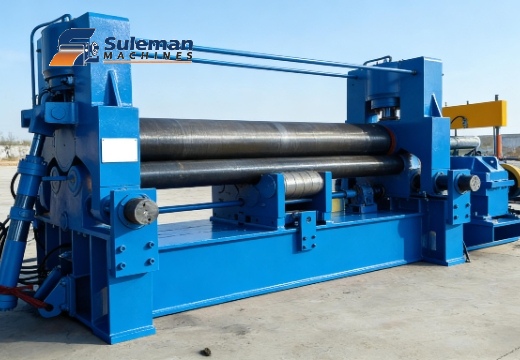 Why Wind Power Projects Demand "Universal" 3-Roll Plate Rollers
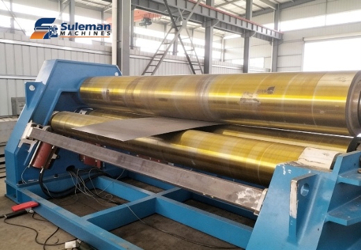 he "Max Thickness" Trap: Why Your 20mm Plate Roller is Failing Your 16mm Jobs